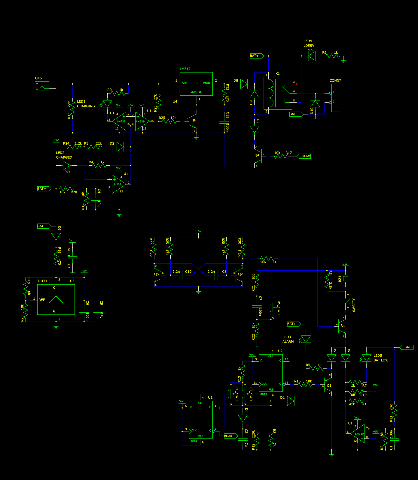
Reverse engineering a backup sump pump controller

The circuit board in this article came from a battery-powered backup sump pump controller. This device is generally used in conjunction with a mains-powered sump pump. Should the mains-powered pump fail, this device will switch on a battery-powered backup sump pump once the water level in the sump reaches a certain level. This device also charges the battery from mains and monitors the battery voltage. Note on reference designators: Many chips contain multiple copies of the same circuit (for example, 74HC00 NAND chip). Each copy will be shown individually, but will have the same reference designator. To distinguish these copies, the lowest pin number belonging to that copy will be placed in brackets after the reference designator. For example, the gates a 74HC00 with reference designator U1 will be referred to as U1[1], U1[4], U1[8], and U1[11] Operation The device does the following things: Charge the battery from mains when the battery voltage drops below 13.5 volts and stop...


