Reverse engineering a backup sump pump controller
Note on reference designators: Many chips contain multiple copies of the same circuit (for example, 74HC00 NAND chip). Each copy will be shown individually, but will have the same reference designator. To distinguish these copies, the lowest pin number belonging to that copy will be placed in brackets after the reference designator. For example, the gates a 74HC00 with reference designator U1 will be referred to as U1[1], U1[4], U1[8], and U1[11]
Operation
The device does the following things:- Charge the battery from mains when the battery voltage drops below 13.5 volts and stop charging when the battery voltage is above 14 volts
- Switch on the backup pump and sound an alarm whenever the float switch indicates that the sump is full or when the user presses the "pump test" button
- Continue sounding the alarm until the user resets or disables it
- Disable the pump and sound the alarm when the battery voltage goes below 9.4 volts
Schematic
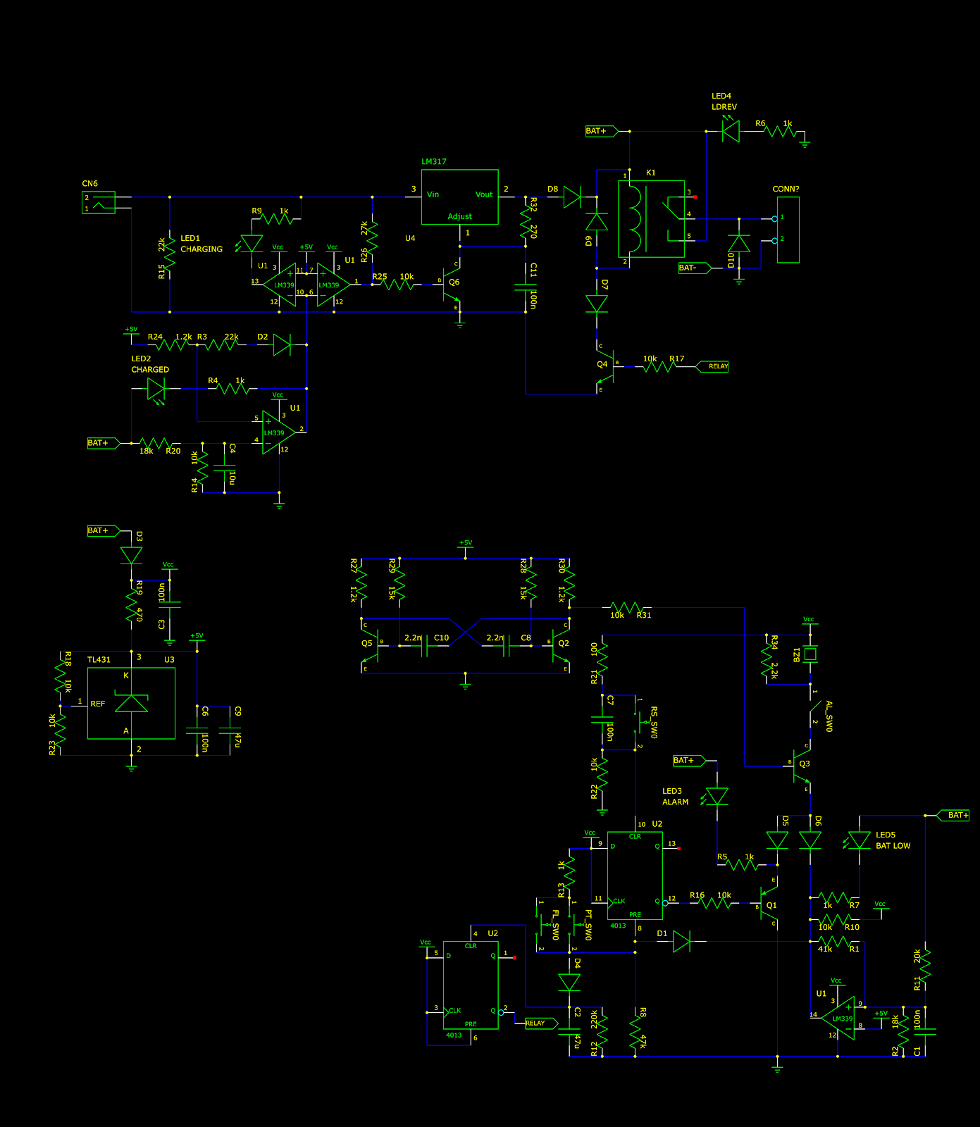
The schematic can be divided into three sections: the battery charger, the pump controller, and a voltage regulator. The full schematic is shown below:Regulator and voltage reference
The 5 volt rail is generated with a TL431 chip. The TL431 passes current between its cathode and anode until the voltage between the reference input and the anode is 2.5 volts. Since no current flows into the reference pin, and the reference pin is connected to a voltage divider between the cathode and anode, the voltage between the cathode and the anode will be 5 volts.
Battery charger and relay
As explained above, the battery charger must monitor the battery voltage to determine when to charge. This is done using U1[2]. Suppose the output of U1[2] is high-impedance. The output will be pulled up to the battery voltage by LED2 and R4. Since the battery voltage is greater than 5 volts, D2 will not conduct and the non-inverting input will be at 5 volts. When the battery voltage goes above 14 volts, the inverting input will go above 5 volts, and U1[2] will pull its output low. Then, D2 will begin to conduct and pull the noninverting input down through R3 to about 4.8 volts. This lowers the threshold to 13.5 volts, creating a hysteresis. When the output of U1[2] is low, current will also flow through LED2 and R4, indicating that the battery is charged.
When the battery is fully charged, U1[2] pulls the inverting inputs of U1[10] and U1[1] low, so the outputs of U1[10] and U1[1] are both high-impedance. If power is connected to CN6, current will flow through R26 and R25, turning on Q6. This pulls the ADJ pin of the LM317 to ground. The output pin of the LM317 is thus regulated to 1.25 volts. Since this is lower than the battery voltage, D8 does not conduct and the battery does not charge.
However, when the battery is not full, U1[1] pulls its output low. This turns Q6 off, and the voltage on the ADJ pin is allowed to float. In this configuration, the voltage between the ADJ and output pins is much less than 1.25 volts, and the LM317 turns on fully. The current into the battery is only limited by the internal current limit of the LM317. U1[10] also pulls its output low, drawing current through the CHARGING LED.
When Q4 receives a signal from another part of the circuit, it turns on the relay K1, switching battery power to the pump. D10 acts as a flyback diode for the pump and D9 acts as a flyback diode for the relay coil. D7 keeps the relay from turning on when the battery is accidentally connected backwards. If the relay did turn on, it would short the battery through D10, which would destroy the diode and blow the fuse. If the leads are connected backwards, LED4 would light up.
Pump and alarm controller
This section contains two 4013 D-type flip flops. However, neither is configured as a D-type flip flop. U2[1] has its preset input tied to Vcc, so its Q output will be high and its Q and Q output is low and the Q output is high and the
Q2, Q5, C10, C8, R27, R28, R29, and R30 form an oscillator circuit that generates the tone for the alarm signal. The oscillator runs even when the alarm is not running or has been disabled by the user.
When the float switch (FL_SW0) indicates that the sump is full, it closes and C2 charges through D4 and R13. When the voltage on C2 is high enough, U2[1] is cleared and its ALARM LED. Current also flows through D5 and is modulated by Q3 to produce a beep in the piezo element BZ1. The user can open the switch AL_SW0 to disable the alarm. Once the flip flop U2[8] is set, the alarm continues until the user presses the RS_SW0 button, which resets the flip flop and stops the alarm.
This section also monitors the battery voltage and disables the pump when it is too low. This is done with U1[8]. When the battery voltage goes below abount 9.4 volts, U1[8] switches its output to ground, passing current through D6 and turning on the alarm. Current also flows through D1, connecting the output of the float switch to ground. This prevents the pump from turning on when the battery is low. U1[8] also draws current through the BAT LOW LED to indicate that the battery is low.


Comments
Post a Comment