Powering mains-voltage LED Christmas lights from a 12 volt battery
In this article I will present an inverter circuit I built to power mains-voltage LED light strings from a 12 volt battery. Unlike a traditional inverter, this device operates at a higher frequency, eliminating flicker in cheap LED light strings. The device can also switch the output of the inverter through a TRIAC, allowing the device to be programmed to vary the brightness of the light string. Depending on the configuration of the LED lights in the string, it can also vary the brightnesses of different parts of the LED string independently of one another.
The schematic can be downloaded here and the program for the ATTiny can be downloaded here
Principle of operation
Generating the high voltage
This inverter uses a transformer to generate a high voltage from a 12 volt power supply. This is done by switching the low-voltage coil of the transformer through an H-bridge, which consists of 2 N-channel MOSFETS and 2 P-channel MOSFETS:
On the left, we have a 500Hz source that drives the gates of the first pair of N- and P-channel MOSFETS. If the source outputs 12 volts, then the P-channel MOSFET will be off and the N-channel MOSFET will be on, so the output of the first pair will be zero volts. As a result, the second P-channel MOSFET will be on and the second N-channel MOSFET will be off, and the output of the second pair will be 12 volts. This connects the 12 volt supply across the transformer. However, when the source outputs zero volts, the output of the first pair will be 12 volts and the output of the second pair will be 0 volts. This still connects 12 volts across the transformer, but in the opposite polarity. Thus, the voltage across the transformer coil will alternate between 12 and -12 volts 500 times per second. The transformer steps up the voltage at its input by about 10 times, so the voltage output to the light string is a 500Hz square wave with an amplitude of about 120 volts.
The 500Hz reference signal is generated by an ATTiny85 microcontroller. However, the output of the microcontroller is limited to between 0 and 5 volts, so if I connected the output of the microcontroller directly to the input of the first stage, the P-channel MOSFET would never turn off, because the voltage on its gate would always be less than the voltage on its source, which is 12 volts. This would cause a short circuit when the N-channel MOSFET turns on. To solve this problem, I needed to make a level shifter circuit to generate a 12 volt signal from the ATTiny's 5 volt output:

When the output of the ATTiny is high, the lower NPN transistor is turned on, pulling the input to the first pair of MOSFETs low. Since the emitter and the base of the leftmost NPN transistor are both at 5 volts, it does not turn on, and no current flows through the base of the PNP transistor. This prevents a short circuit between the power rails when the output is high.
When the output of the ATTiny is low, the lower NPN transistor is turned off. The leftmost NPN transistor now acts as an emitter follower, so the voltage at its emitter is now equal to to 5 volts minus the base-emitter drop (about 0.6 volts). This creates a current of about 4.4 mA through the resistor on the emitter of the NPN transistor. Thus, the transistor acts as a current source pulling about 4.4 mA from the base of the PNP transistor, turning it on and pulling the input to the first pair of MOSFETS to 12 volts.
Varying the brightness of the LEDs
The ATTiny can vary the brightness of the LEDs by switching the output of the transformer through a TRIAC. A TRIAC has two main terminals (MT1 and MT2) and a gate terminal (G) and acts as a bidirectional switch. Once the TRIAC is turned on by current into or out of its gate pin, it connects the MT1 and MT2 pins together until the current drops below its holding current.
Since the current through the load crosses through zero between the positive and negative half-cycles of the output voltage, the TRIAC turns off at the end of each half-cycle. Thus, the ATTiny must trigger the TRIAC in each half-cycle. If the ATTiny triggers the TRIAC close to the beginning of the half-cycle, then the LEDs remain on for most of the cycle and they appear at full brightness. If the TRIAC is triggered near the end of the cycle, then the LEDs remain on only for a short period of time, and they appear dimmer. Additionally, the point at which the TRIAC is triggered can be different in the positive and negative half cycles.
Light string
Depending on the configuration of the LEDs, the device may only be able to control the brightness for the whole string at once. For example, the light strings I am using consist of four parallel sections of 50 LEDs in series. Since all of the LEDs are connected in the same direction (for example, from live to neutral), then current only flows in one half-cycle anyway. To fix this, one could swap live and neutral between sections or between strings.
Fancier LED strings may also contain recifiers, smoothing capacitors, or even switching power supplies. In these cases, the dimming feature will not be useful.
Construction
For this project I used a transformer from a 12 volt power supply. The low-voltage output of the transformer was soldered to a little board with a recitifier and a capacitor on it. I kept the capacitor, but desoldered the rectifier diodes and scraped the solder mask off of the board. I took all four MOSFETS from the motherboard of an old laptop, soldered them to the board, and connected their gate pins appropriately:

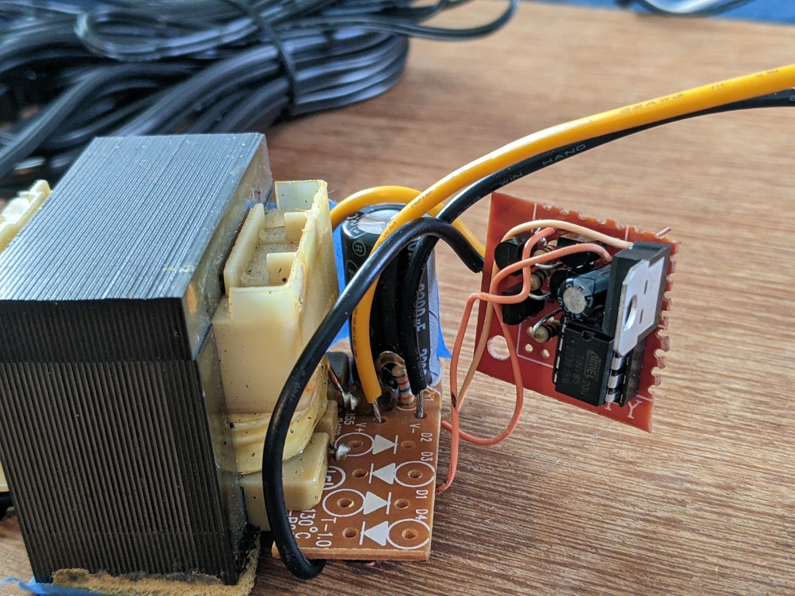
I soldered the ATTiny, the level shifter, and the TRIAC to a small piece of perfboard and connected it to the H-bridge board. I also connected the TRIAC in series with the mains output. Power is supplied to the H-bridge by the thick yellow and black wires next to the capacitor. The other pair of black and yellow wires connect the TRIAC in series with the output.


Comments
Post a Comment