Divide-by-n counter with a fixed duty cycle
A divide-by-n counter is a circuit that takes a digital clock signal with a frequency f and a number n and produces a digital output signal with a frequency of f/n. For example, the waveforms below are the input and output of a divide-by-5 counter that produces an output pulse every 5 input pulses.

However, this approach produces a output waveform with a duty cycle that decreases as n increases. In some cases, it may be necessary to produce an output with an exact 50% duty cycle that does not change with n:

In this article, I will describe a 9 bit divide-by-n counter circuit (where n is between 2 and 511) that produces an output with a 50% duty cycle.
Note on reference designators: Many logic chips contain multiple copies of the same circuit (for example, 74HC00 NAND chip). Each copy will be shown individually, but will have the same reference designator. To distinguish these copies, the lowest pin number belonging to that copy will be placed in brackets after the reference designator. For example, the gates a 74HC00 with reference designator U1 will be referred to as U1[1], U1[4], U1[8], and U1[11]
Schematic and operation
The schematic is shown below:
Operation of the 40103 chip
The 40103 chip used in this circuit is a presettable down counter. The chip contains an internal counter, and whenever the internal counter is equal to 0, the J0-J7 inputs can be loaded asynchronously (immediately) to the internal counter by driving the
When n is even
When n is an even number, then the general approach is to toggle the output every n/2 input clock cycles. When n is even, D0 is 0, so the output of U2[1] is high. The n/2 (which can be easily computed by simply ignoring the least significant bit and shifting the rest down). The D0=0, D1=0, D2=1), one gets the following waveforms:

The internal counter is only zero for a very short period of time, because as soon as the
When n is odd
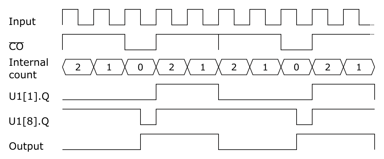
When n is odd, the general approach is to switch the output on for (n-1)/2 cycles and switch it off for (n+1)/2 cycles and then correct the duty cycle of the output by switching the output on half a cycle early. When n is odd, D0 is 1, so only when the (n-1)/2 as soon as the internal counter becomes zero. Thus, the (n-1)/2. However, when the (n+1)/2 cycles.

However, the duty cycle of the output is not 50%. To correct for this, the output is turned on half a cycle early. When Q output of U1[1] is high, its Q output turns off, and the output of U2[11] is forced high. Since the


Comments
Post a Comment